Fundamentals of Computer Systems Year 2
Table of Contents
1 Adders
Half adder
- A half adder is a circuit with two logic gates: XOR and AND.
- It is an adder because it adds two bits together to produce the result and a carry bit.
- The following are the ciruit and truth table for a half adder.
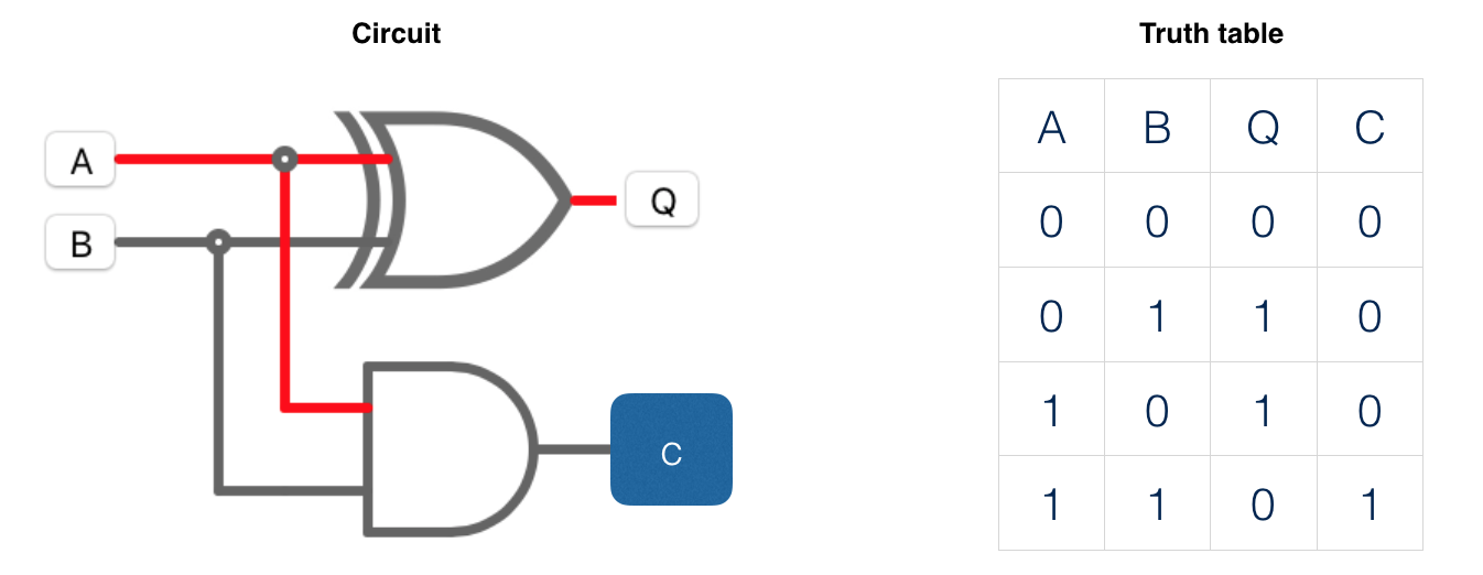
- Half adder is so named because it does not have the carry bit as input.
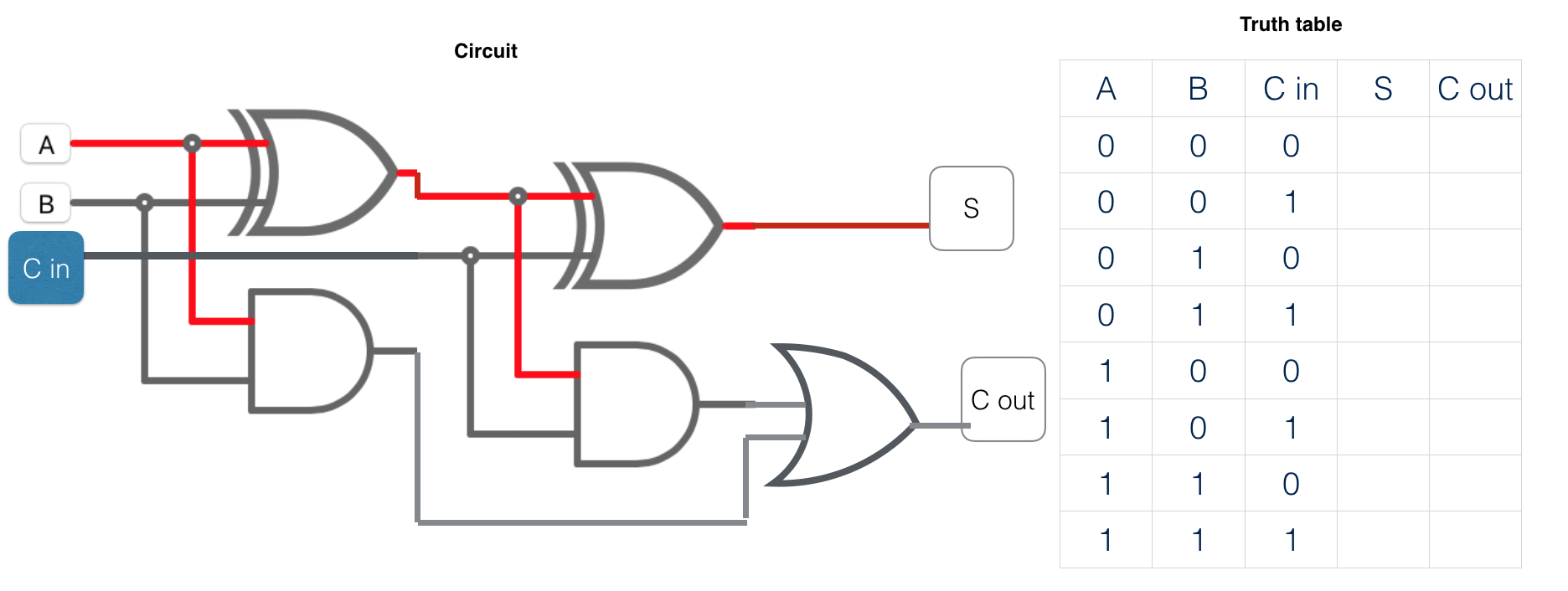
Full adder
- A full adder is a circuit with two half adders plus a OR gate.
- It has three bits as input.
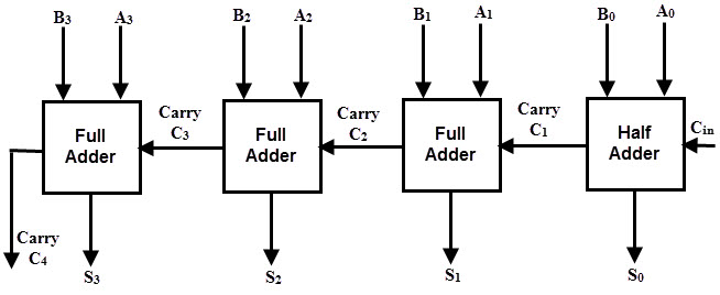
- if four of those full adders are connected, we can add 4-bit numbers.
2 D-type flip flops
- A flip flop is a logic circuit that can store one bit and flip between two states: 0 and 1.
- It has two inputs: a control input and a clock signal input the clock is to synchronise the change of state
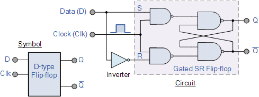
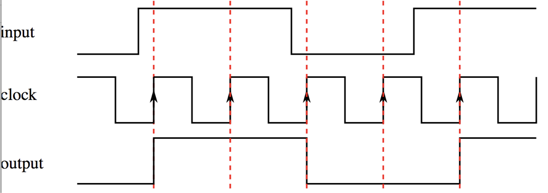
- A D-type flip flop (D for data) only changes the output from 0 to 1 or vice versa only when the clock at the beginning of a clock signal (rising edge). During a rising edge of the clock, its input D is transferred to the flip-flop's output Q.
- when the clock is not at the rising edge, the input is not changed.
In Summary:
- Since output Q only takes a new value if the value D has changed at the point of a clock pulse, this means the clock pulse will freeze therefore ‘store’ the input value D until the next clock pulse. If D is the same on the next clock pulse, the flip flop will hold the same value.
- A flip flop made of several NAND gates and can store 1-bit memory
- To store 8 bits, 8 flip flops are needed.
- Used in making of registers and RAM.